
The rotational motion of the vehicle is synthesized by three independent rotational motions, representing the rotation, pitch and roll motion of the vehicle. In the inertial coordinates, the position of the center of gravity of the vehicle is defined by an appropriate amount. The axis points to the left side of the wheel, and the axis points vertically to the upper part. The axis points to the front of the vehicle along the longitudinal axis of the tire. The center of the tire coordinate is the contact point between the tire and the ground. The axis points to the upper part of the computer interface, and the axis is in the same direction as the acceleration of gravity. The X’ axis points to the front of the vehicle along the longitudinal axis of the vehicle.

The center of the vehicle coordinates is the position of the center of gravity of the vehicle. The X axis points to the right side of the computer interface, the Y axis points to the upper part of the computer interface, and the Z axis is in line with the direction of gravity acceleration. The global coordinate center is the center of the interface initialized by the Pc-Crash software, and the plane is the ground. In PC-Crash, to simplify the definition of vehicle geometry model, three coordinate systems, global coordinates OXYZ, vehicle coordinates and tire coordinates are introduced, as shown in Figure 2.

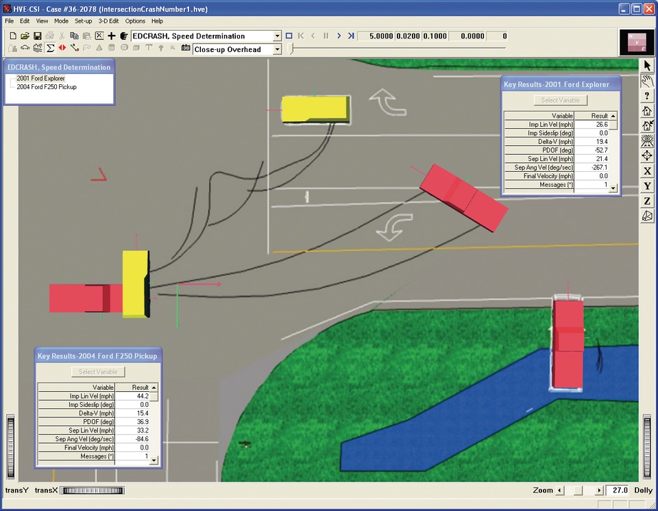
Interface of PC-Crash software.Īnd driver’s operation status of each participant obtained by the accident reconstruction can be read. Information such as the exercise parametersįigure 1. The reproduction results are shown in an animated form, which is more intuitive and easy to understand. Through the information of the ground tire traces at the accident site, the final position of the participants, the damaged parts of the vehicles and the damage parts of the pedestrians, the accident collision process is optimized, and the accident process that meets the information of the legacy of the accident is finally obtained. The final position of the accident participants is used to estimate the motion process before the collision ( Figure 1). Based on the principles of momentum conservation and energy conservation, the relevant equations of the accident participants are established.
DOWNLOAD FREE ACCIDENT RECONSTRUCTION SOFTWARE SOFTWARE
The theoretical basis of PC-Crash software is kinematics theory and dynamics theory. It can perform collision analysis such as automobile and pedestrian. of the University of Graz, Austria, based on the Kudfich-Slibar model. The PC-Crash software is an accident reconstruction software developed by H. The Theoretical Basis of PC-Crash Software and Its Vehicle Accident Reconstruction The most serious injuries in the 11 pedestrians were AIS3+.Ģ. The biggest injury to the injured pedestrians was MAIS3+. In the end, 30 cases of human-car collision accidents were selected, including 19 cases of death accidents. The following conditions are met for the collision of people and vehicles:ġ) The accident vehicle models are cars, SUVs, MPVs, of which cars are mainly used Ģ) The selected accidents are collisions with pedestrians at the front of the vehicle, and no pedestrian crushing occurs during the collision ģ) In each case of pedestrian accident, the pedestrian participation is one person and the pedestrian is an adult. Taking the typical vehicle crash accident conditions as the basic criteria, the pedestrian AEB system is used to configure the vehicle to select the accident. The purpose of accident reconstruction in this paper is to obtain parameters such as the kinematic parameters related to people and vehicles before the accident, and provide data for the evaluation of the pedestrian AEB system. Selection of People’s Car Accident Samples


 0 kommentar(er)
